SysML FAQ: What is the relationship between SysML and UML?
Short Answer:
Contrary to MBSE and tool-vendor Muddle-Driven Marketecture hype, the differences between the SysML and UML modeling languages are more lightweight and dialectical in nature than heavyweight and substantive. This should be expected since SysML was originally designed to be used by Systems Engineers collaborating with Software Engineers applying UML for software analysis and design, and SysML is defined as a modestly extended pragmatic subset of UML 2. (See SysML FAQ: Can SysML and UML model elements be combined in the same model? Indeed, although SysML adds two useful diagram usages to UML (Requirements diagrams extend UML Class diagrams; Parametric diagrams extend UML Class & Composite Structure diagrams), the other diagrams that SysML borrows from UML are either largely reused without modification (e.g., Use Case, Sequence, State Machine diagrams) or are modestly tweaked with lightweight customizations called stereotypes that lack substantive semantics (e.g., renaming Classes as Blocks and adding lightweight syntax and semantics for physical item flows; adding stereotypes to Activity diagrams without bona fide executable semantics).
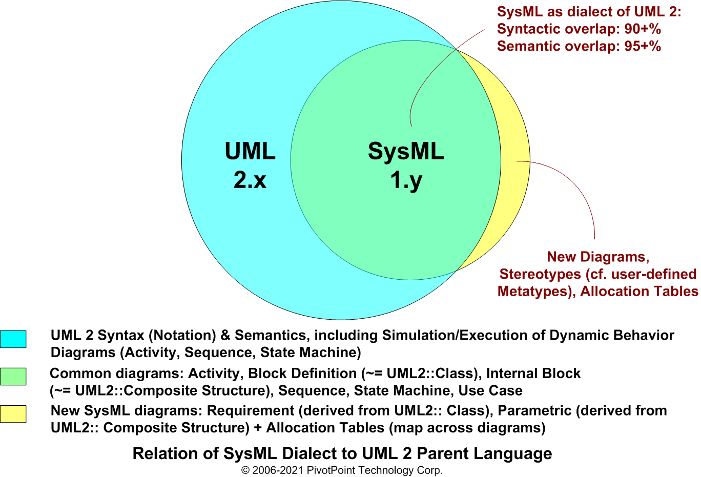
SysML is defined as a lightweight dialect (Profile) of UML 2.x, the industry-standard modeling language for software-intensive applications. (The SysML Profile is lightweight in the sense that the changes that it makes to the underlying language are relatively modest in scope and extent, using a small number of simple stereotypes, tagged values, and constraints. Compare and contrast with a heavyweight Profile, which could significantly impact how the underlying language is used.) The advantage of defining SysML as a UML Profile is that it can reuse the relatively mature notation and semantics of UML 2.x, which many modeling tool vendors have already implemented. The disadvantage of specifying SysML as a UML Profile is that SysML inherits many of the problems associated with UML 2.x, such as gratuitously complex notation, imprecise semantics, and a dysfunctional diagram interoperability standard (XMI).
• SysML expresses systems engineering semantics (interpretations of notations) better than UML. It reduces UML's software bias and adds two new diagram types for requirements management and performance analysis: Requirement diagrams and Parametric diagrams, respectively.
• SysML is smaller and easier to learn than UML. Since SysML removes many software-centric and gratuitous constructs, the overall language is smaller as measured in diagram types (9 vs. 13) and total constructs.
• SysML model management constructs support the specification of models, views, and viewpoints that are architecturally aligned with IEEE-Std-1471-2000 (IEEE Recommended Practice for Architectural Description of Software-Intensive Systems).
SYSML DIAGRAM
PURPOSE
UML DIAGRAM ANALOG
Useful for functional analysis.
Compare Flow Block Diagrams (FBDs) and Extended Functional Flow Block diagrams (EFFBDs), already commonly used among systems engineers.
Activity diagram
Useful for system analysis and design.
Class diagram
Useful for system analysis and design.
Composite Structure diagram
Useful for model management.
Package diagram
Useful for requirements engineering, including requirements verification and validation (V&V).
Useful for system analysis and design.
Sequence diagram
Useful for system design and simulation/code generation.
State Machine diagram
Useful for specifying functional requirements. (Note potential semantic overlap with functional Requirements specified in Requirement diagrams.)
Use Case diagram
Useful for facilitating automated verification and validation (V&V) and gap analysis.
Object diagram
Communication diagram
Component diagram
Deployment diagram
Interaction Overview diagram
Profile diagram
Timing diagram
TOGAF and ARCHIMATE are trademarks of The Open Group.
ENTERPRISE ARCHITECT is a trademark of Sparx Systems Pty Ltd. MAGICDRAW and CAMEO are trademarks of No Magic, Inc. RATIONAL RHAPSODY is a trademark of IBM.
All other trademarks are the property of their respective owners.