SysML FAQ: What is a Parametric diagram (PAR) and how is it used?
What is a SysML Parametric Diagram?
Definitions
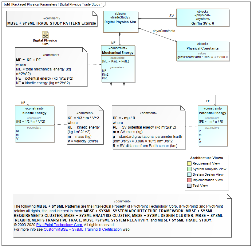
Constraint Block: A Constraint Block (notation: rectangle with keyword = «constraint») defines a mathematical rule (Constraint) and rule Parameters, where the latter are bound to Block Value Properties so that changes to one Block Value Property will be propagated to other Block Value Properties in a manner consistent with the mathematical rule. (See Executable Semantics below.)
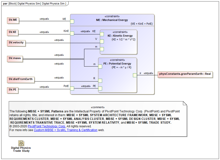
Parametric diagram (par): An Parametric diagram is a specialization of an Internal Block Diagram (IBD) that enforces mathematical rules (Constraints) defined by Constraint Blocks across the internal Part Value Properties bound by the Constraint Block Parameters.
- Binding Connectors (keyword = «equal») between Constraint Block Parameters and internal Part Value Properties effect constraint satisfaction (propagation)
Purpose
The purpose of Parametric diagrams (PARs) is to enforce mathematical rules across Block Value Properties. When used correctly BDDs + IBDs + PARs are recursively scalable and mathematically simulatable. (See Executable Semantics below.)
Diagram Properties
| Diagram Name | Diagram Type | UML 2 Analog | SDLC Usage | Essential AGILE SYSML? |
Dynamic Sim † |
Math Sim ‡ |
Auto Code Gen |
Rigor | Semi | Informal |
|---|---|---|---|---|---|---|---|---|---|---|
| Parametric Diagram (par) | Static Structure [White Box Usage] |
N/A | System Analysis, System Design |
|||||||
Usage Notes
BDD Constraint Block Definition vs. PAR Constraint Block Usage Dichotomy
- A BDD defines a Constraint Block’s mathematical rule (Constraint) and the rule's Parameters
- a PAR specifies the Binding Connector usages among Constraint Block Parameters and the Part Value Properties that are restricted by them.
Compare and contrast: BDD Block Definition vs. IBD Block Usage dichotomy; UML Specification-Realization and Type-Instance dichotomies
| BEST PRACTICE PATTERNS |
ANTI-PATTERNS |
|---|---|
| * Apply Constraint Blocks and PAR diagrams to System Designs after the BDD-IBD system architecture skeletons have stabilized. | * Applying Constraint Blocks and PAR diagrams in isolation (i.e., not integrated with BDD-IBD system architecture skeletons. |


