SysML FAQ: Can SysML and UML model elements be combined in the same model?
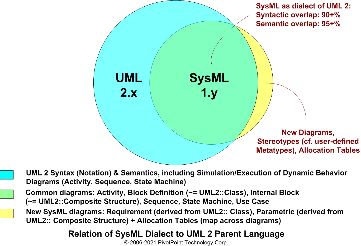
In theory, SysML and UML model elements can be synergistically combined in the same model. Indeed, this was one of the language design goals of the SysML Partners' open source specification project:
• Support SysML + UML mixed language usage:
Ensure that SysML constructs can be synergistically combined with UML constructs in a model shared by Systems Engineers and Software Engineers, where the former use SysML and the latter use UML. The synergistic combination of SysML and UML should maximize requirements traceability and minimize semantic overlap between the two languages. “SysML Language Design Goals”, SysML Partners
Select a UML modeling tool that correctly implements SysML as a UML2 compliant profile and allows you to populate SysML diagrams with UML constructs and populate UML diagrams with SysML constructs.
UML modeling tools that support SysML vary widely in this regard, with some being more restrictive than others since the OMG specifications generally defer this sort of implementation detail to vendors. Check out SysMLtools.com for candidate SysML modeling tools that support SysML + UML2 mixed language usage.- Organize your model into well-defined Views along the lines of the following, where UML and SysML diagrams are combined in a complementary manner:
(See SysML «view» stereotype of Package for View notation and semantics.) Modelers should feel free to modify the following Views and their contents consistent with their chosen Model-Based Systems Engineering (MBSE) and/or Model-Driven Development (MDD) methods.- Requirements «view»: Systems Engineers are primarily responsible for the completeness, correctness, and integrity of this View and the definition of its corresponding Viewpoint. Candidate diagram type contents include, but are not limited to, the following: UML/SysML Use Case and SysML Requirement diagrams.
- Requirements «view»: Systems Engineers are primarily responsible for the completeness, correctness, and integrity of this View and the definition of its corresponding Viewpoint. Candidate diagram type contents include, but are not limited to, the following: SysML Block Definition, Internal Block, Parametric, Activity, and State Machine diagrams. Other SysML diagrams may be added as needed.
- System Design «view»: Software Engineers are primarily responsible for the completeness, correctness, and integrity of this View and the definition of its corresponding Viewpoint. Candidate diagram type contents include, but are not limited to, the following: UML Class, Composite Structure, Sequence, Timing, State Machine, Component, and Deployment diagrams.
- ...other Views as needed for Implementation, Testing, etc.
- Ensure bi-directional Requirements Traceability on both sides of the System V-Model:
The modeling team should designate and consistently apply appropriate dependencies for full requirements traceability across all Views. You can synergistically effect full traceability across the complementary Views described above by applying the following traceability dependency patterns within and across Views:- Traceablity within the Requirements «view»: Define Refine («refine») dependencies between functional Requirements and the Use Cases that refine them.
- Traceability between the Requirements «view» & System Analysis «view»: Define Satisfy («satisfy») dependencies between Requirements and the Activities and Blocks that satisfy them. (Optional: As per common UML best practice, you can also define a Realization or Refine dependency between a Use Case and any Activity that realizes or refines it.)
- Traceability between the System Analysis «view» & System Design «view»: Define Refine dependencies between the SysML Blocks and Activities defined in the System Analysis «view» and the UML Classes and Sequences that refine them in the System Design «view».
- Traceability across other Views: Since Refine is a transitive relationship, System Design «view» model elements can be further refined and traced across other Views (e.g., Implementation/Construction, Deployment, Testing, etc.).
Combined SysML + UML2 Example Request: If you are interested in pursuing the technical approach outlined above, but need a combined SysML + UML2 example to better understand how it works, please contact us. If we receive sufficient requests for a combined SysML + UML2 example (say 10+ requests), we will post one to the SysML Forum.


