SysML FAQ: What is a Block Definition Diagram (BDD) and how is it used?
What is a SysML Block Definition diagram?
Definitions
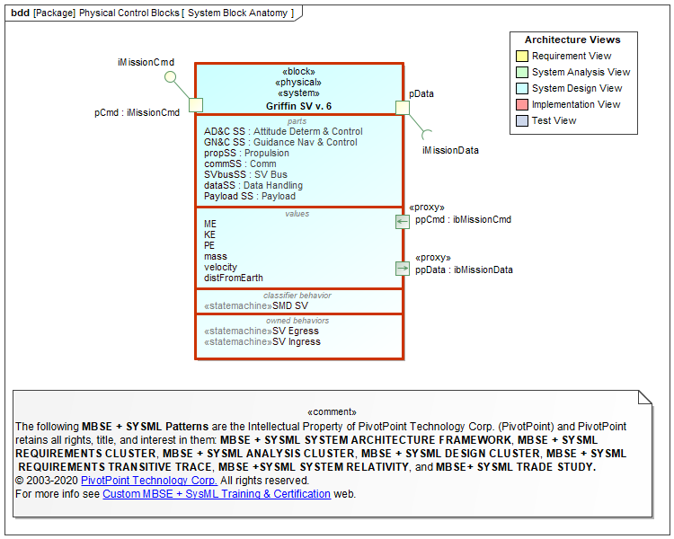
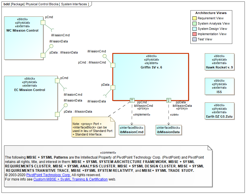
Block: A Block (notation: rectangle with keyword = «block») represents a system component, a modular structural unit that encapsulates its contents (Properties, Behaviors, Constraints) and supports first-class (i.e., can be drawn and directly manipulated in the model repository) Interfaces. Behaviors encapsulated by Blocks include: Operations, Signals, and State Machines. The unique interaction points for attaching and connecting ("wiring") Block Interfaces are called Ports.
- Blocks can specify software, hardware, mechanical, and wetware (persons, organizations, facilities) components.
- Blocks support both Provided (implemented or realized) and Required (used) Interfaces for both information and physical flows.
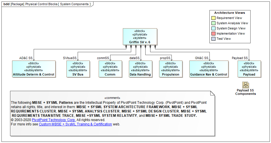
- Blocks can be recursively decomposed into Parts, where each Part must also be defined by a Block. (See Usage Notes below.)
Block Definition Diagram (bdd): A Block Definition Diagram is a static structural diagram that shows system components, their contents (Properties, Behaviors, Constraints), Interfaces, and relationships.
- Blocks can be recursively decomposed ("nested") into Parts by alternating between Block Definition Diagram (BDD) definitions and Internal Block Diagram (IBD) usages (See Usage Notes below).
- Behaviors can either be encapsulated by Blocks (e.g., Operations, Signals, and State Machines) or Allocated (via «allocate» Dependency) to Blocks (e.g., Activities/Actions) directly or indirectly (via Interfaces).
- Blocks can be mathematically constrained via Constraint Blocks to produce mathematically simulatable Parametric diagrams.
- compare and contrast: UML 2 Class and Component diagrams; SA/SD System Context & Structure Chart diagrams; IDEF IDEF1X diagrams.
Purpose
The purpose of Block Definition Diagrams is to specify system static structures that be used for Control Objects, Data Objects, and Interface Objects. When properly applied (See Usage Notes below), Block diagrams are recursively scalable and mathematically (parametrically) simulatable (See Executable Semantics below).
Diagram Properties
| Diagram Name | Diagram Type | UML 2 Analog | SDLC Usage | Essential AGILE SYSML? |
Dynamic Sim † |
Math Sim ‡ |
Auto Code Gen |
Rigor | Semi | Informal |
|---|---|---|---|---|---|---|---|---|---|---|
| Block Definition Diagram (bdd) | Static Structure [Black Box Definition] |
Class [moderate mods] |
System Analysis, System Design |
|||||||
Usage Notes
BDD Block Definition vs. IBD Block Usage Dichotomy
BDDs and IBDs complement each other (cf. black-box vs. white-box) and support recursive structural decomposition techniques during System Analysis & Design.
- A BDD defines a Block’s Properties, including its Part Properties (strongly owned Parts) and Reference Properties (shared Parts)
- IBD specifies Part Properties and Reference Properties usages or roles in the structural context of the Block that encapsulates them. Stated otherwise, Part Properties and Reference Properties in an IBD can have a different usages or roles depending upon how they are realized ("wired") in the IBD.
- Compare and contrast UML Specification-Realization and Type-Instance dichotomies
| BEST PRACTICE PATTERNS | ANTI-PATTERNS |
|---|---|
| * Aggressively apply Object Triad Pattern triage techniques to Blocks in order to separate Control Objects, Interface Objects, and Data Objects. | * Conflate Control Object, Interface Object, and Data Object Blocks. |
| * Recursively decompose ("nest") Block hierarchies by alternating between BDD definitions and IBD usages. | * SA/SD DFD Anti-Pattern (a.k.a., "Back to the Future circa 1980" Anti-Pattern) = Define Activity diagrams as Functional Flow diagrams without Parttions that represent Control Objects. |
| * Allocate all Activities to Partitions that represent Conrol Object Blocsk. | * Bloctivity Anti-Pattern = Conflate Block and Activity syntax and semantics. |
