SysML FAQ: What are the SysML diagram types?
What are the SysML diagram types?
Question Variant(s): How do the SysML diagrams compare and contrast?; What are SysML Allocation Tables and what are they used for?
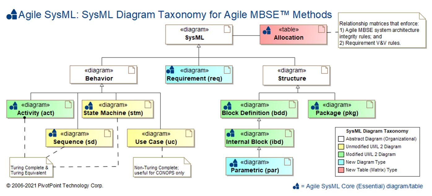
The SysML is composed of nine (9) diagram types and Allocation Tables for mapping language elements across diagram types:
- Requirement diagram (req)
- Structure Diagrams
- Behavior Diagrams
- Allocation Table
The SysML Diagram Taxonomy comparison table below explains the similaries and differences among the various SysML diagram types.
SysML Diagram Taxonomy
The SysML is composed of nine (9) diagram types and Allocation Tables for mapping language elements across diagram types:
| Diagram Name | Diagram Type | UML 2 Analog | SDLC Usage | Essential AGILE SYSML? |
Dynamic Sim † |
Math Sim ‡ |
Auto Code Gen |
Rigor | Semi | Informal |
|---|---|---|---|---|---|---|---|---|---|---|
| Requirement diagram (req) | Static Structure [Declarative] |
N/A | Requirements Analysis | |||||||
| Use Case diagram (uc) | Behavior * [Non-Simulatable] |
Use Case | Requirements Analysis | |||||||
| Activity diagram (act) | Dynamic Behavior [Simulatable] |
Activity [minor mods] |
System Analysis, Functional Analysis, System Design |
|||||||
| Sequence diagram (sd) | Dynamic Behavior [Simulatable] |
Sequence | System Design | |||||||
| State Machine diagram (stm) | Dynamic Behavior [Simulatable] |
State Machine | System Analysis, System Design |
|||||||
| Block Definition Diagram (bdd) | Static Structure [Black Box Definition] |
Class [moderate mods] |
System Analysis, System Design |
|||||||
| Internal Block Diagram (ibd) | Static Structure [White Box Usage] |
Composite Structure [moderate mods] |
System Analysis, System Design |
|||||||
| Parametric Diagram (par) | Static Structure [White Box Usage] |
N/A | System Analysis, System Design |
|||||||
| Package diagram (pkg) | Static Structure [Grouping] |
Package [minor mods] |
All SDLC phases | |||||||
| Allocation Table | N/A [Relationship Matrix] |
N/A | All SDLC phases | |||||||
†: Dynamic Simulation (a.k.a. Dynamic System Simulation) refers to the capability of a computer program to execute the time-varying behavior of a system of interest. In general, with the exception of Use Case diagrams, SysML and UML 2 Behavior diagrams are potentially capable of Dynamic System Simulation.
‡: Mathematical Modeling & Simulation (a.k.a. Mathematical ModSim, Mathematical M&S, Parametric Simulation) refers to the capability of a computer program to execute the a mathematical model of the behavior of a system of interest, where the model is defined as a set of mathematical equations. When properly defined and applied, Parametric diagrams are capable of Mathematical ModSim; no other SysML or UML 2 diagrams are capable of this.
*: Although Use Case diagrams are generally classified as Behavior diagrams by both the OMG SysML and UML 2 specifications, their Behavioral semantics are ambiguous and incomplete. Whereas Activity, Sequence, and State Machine diagrams are Turing Complete and their dynamic behavior can be simulated or executed, Use Cases diagrams are not Turing Complete and are not simulatable.
TOGAF and ARCHIMATE are trademarks of The Open Group.
ENTERPRISE ARCHITECT is a trademark of Sparx Systems Pty Ltd. MAGICDRAW and CAMEO are trademarks of No Magic, Inc. RATIONAL RHAPSODY is a trademark of IBM.
All other trademarks are the property of their respective owners.