SysML + MBSE Overview - What You Need to Know
This section provides an overview of the Systems Modeling Language (SysML), the de facto Model-Based Systems Engineering (MBSE) architecture modeling language standard for specifying large, complex Systems-of-Systems. This SysML + MBSE Overview includes a formal definition and information about SysML core concepts, origins, characteristics, enabling technologies, and variations.
Please contact us with your constructive ideas to correct and improve this section.
Architecture Modeling Language Synopsis: SysML
| Property | Description |
|---|---|
| Definition: | What is the Systems Modeling Language (SysML)?Question Variant(s): What is SysML?; What is OMG SysML?DefinitionSystems Modeling Language (SysML): SysML is a general-purpose architecture modeling language for Systems Engineering applications.
The SysML was originally created by the SysML Partners' SysML Open Source Specification Project in 2003. The SysML was adapted and adopted by the Object Management Group (OMG) as OMG SysML in 2006. For more information about the current version of OMG SysML, see the SysML FAQ: What is the current version of SysML?. |
| Aliases: | N/A |
| Language Classification: | Artificial Language Visual Modeling Language Visual Architecture Modeling Language UML SysML (UML Profile or Dialect) |
| Core Concepts: | The expression the Four Pillars of SysML refers to the four essential diagrams of SysML: Requirement, Activity, Block, and Parametric diagrams. The expression was coined by Cris Kobryn, the chair of the SysML Partners open source specification project, when he observed that 80+% of the time that the SysML Partners discussed SysML language features, they were discussing features in these four diagrams. He further noted that, from an artificial language design perspective, the Activity and Block diagram pillars were more important than the other two, since they were based on proven UML2 diagram techniques that already successfully integrated (allocated) behaviors (functions) to structures.  |
| Diagram Types: | |
| Language Origin: | The Systems Modeling Language (SysML) was created by the SysML Partners, an informal association of Systems Engineering experts and software modeling tool experts that was organized by Cris Kobryn in 2003 to create a profile (dialect) of the Unified Modeling Language (UML) that could be used for Systems Engineering applications. Since Kobryn had previously successfully led the UML 1.x and UML 2.0 language design teams, David Oliver and Sanford Friedenthal of INCOSE asked Kobryn to lead their joint effort to respond to the Object Management Group's UML for Systems Engineering RFP issued in March 2003. As Chair of the SysML Partners, Kobryn coined the language name "SysML" (short for "Systems Modeling Language"), designed the original SysML logo, and organized the SysML core language design team as an open source specification project. For further details about the history of the SysML, see the SysML Partners page on the SysML.org web. |
| Current Specification: | OMG SysML v. 1.6 (See SysML Specifications page.) Level of Rigor: Level of Rigor: Informal
Editor Specification Rating: B Compliance, Conformance & Certification:
|
| Language Characteristics: | • General purpose? • Graphic syntax? • Precise executable semantics? • Open standard? • Supports Rigorous or Robust processes? • Supports Agile or Lean processes? • Tool support? • Interoperable? [Applicable to any System] [Visual notation similar to UML 2] / [Incomplete varies w/ implementation] [Can be adapted] [Can be adapted] [Extensive] / [Poor due to XMI shortcomings] |
| Enabling Technologies: | • UML 2: SysML is defined as a dialect (profile) of UML 2, the industry-standard architecture modeling language for software-intensive systems. |
| Language Usages: | • Primary Users: Systems Engineers • Other Users: Software Engineers, Electrical Engineers, Mechanical Engineers, … • Estimated Number of Users: N/A |
| Language Variations: | (Open Source) SysML: The original SysML specification created by the SysML Partners Open Source Specification project during 2003-2005. OMG SysML: SysML variation adopted by the Object Management Group in 2006 as OMG SysML v. 1.0. Current version is OMG SysML v. 1.6. |
| Tool Support: | See SysML Tools for selected reviews of popular SysML-compliant architecture modeling tools. |
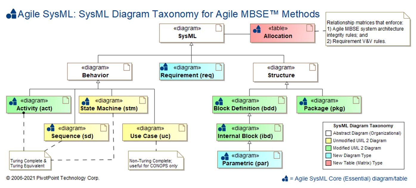
SysML Diagram Taxonomy
The SysML is composed of nine (9) diagram types and Allocation Tables for mapping language elements across diagram types:
| Diagram Name | Diagram Type | UML 2 Analog | SDLC Usage | Essential AGILE SYSML? |
Dynamic Sim † |
Math Sim ‡ |
Auto Code Gen |
Rigor | Semi | Informal |
|---|---|---|---|---|---|---|---|---|---|---|
| Requirement diagram (req) | Static Structure [Declarative] |
N/A | Requirements Analysis | |||||||
| Use Case diagram (uc) | Behavior * [Non-Simulatable] |
Use Case | Requirements Analysis | |||||||
| Activity diagram (act) | Dynamic Behavior [Simulatable] |
Activity [minor mods] |
System Analysis, Functional Analysis, System Design |
|||||||
| Sequence diagram (sd) | Dynamic Behavior [Simulatable] |
Sequence | System Design | |||||||
| State Machine diagram (stm) | Dynamic Behavior [Simulatable] |
State Machine | System Analysis, System Design |
|||||||
| Block Definition Diagram (bdd) | Static Structure [Black Box Definition] |
Class [moderate mods] |
System Analysis, System Design |
|||||||
| Internal Block Diagram (ibd) | Static Structure [White Box Usage] |
Composite Structure [moderate mods] |
System Analysis, System Design |
|||||||
| Parametric Diagram (par) | Static Structure [White Box Usage] |
N/A | System Analysis, System Design |
|||||||
| Package diagram (pkg) | Static Structure [Grouping] |
Package [minor mods] |
All SDLC phases | |||||||
| Allocation Table | N/A [Relationship Matrix] |
N/A | All SDLC phases | |||||||
†: Dynamic Simulation (a.k.a. Dynamic System Simulation) refers to the capability of a computer program to execute the time-varying behavior of a system of interest. In general, with the exception of Use Case diagrams, SysML and UML 2 Behavior diagrams are potentially capable of Dynamic System Simulation.
‡: Mathematical Modeling & Simulation (a.k.a. Mathematical ModSim, Mathematical M&S, Parametric Simulation) refers to the capability of a computer program to execute the a mathematical model of the behavior of a system of interest, where the model is defined as a set of mathematical equations. When properly defined and applied, Parametric diagrams are capable of Mathematical ModSim; no other SysML or UML 2 diagrams are capable of this.
*: Although Use Case diagrams are generally classified as Behavior diagrams by both the OMG SysML and UML 2 specifications, their Behavioral semantics are ambiguous and incomplete. Whereas Activity, Sequence, and State Machine diagrams are Turing Complete and their dynamic behavior can be simulated or executed, Use Cases diagrams are not Turing Complete and are not simulatable.
TOGAF and ARCHIMATE are trademarks of The Open Group.
ENTERPRISE ARCHITECT is a trademark of Sparx Systems Pty Ltd. MAGICDRAW and CAMEO are trademarks of No Magic, Inc. RATIONAL RHAPSODY is a trademark of IBM.
All other trademarks are the property of their respective owners.